Hardware
There are numerous possibilities for connecting a string of LEDs to the Raspberry Pi. What the best connection is depends on type of hardware. Hyperion supports the following connections:
- SPI: Used to directly connect Lightberry, LPD6803, LPD8806, and WS2801 strips.
- USB: Used for AdaLight, Lightpack, Paintpack, and SEDU
- GPIO: Used to connect with Pi-Blaster
- [UART: Used to directly connect WS2812b (The setup turned out to be unstable)]
Note that we prefer a separate power supply for the Pi and the led string in contradiction to what the original Adafruit image shows. The reason for this is that the requested current can vary from near 0.0A (all leds off) to 2.6A (50 leds full white) in a short time. The Raspberry Pi requires a stable input voltage which means that a high quality power supply is needed, or a separate power supply for the Pi and the leds.
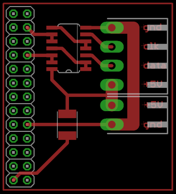
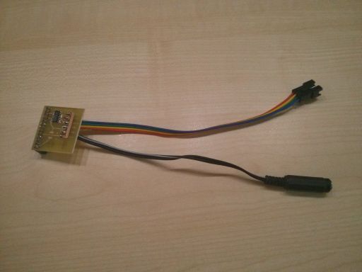
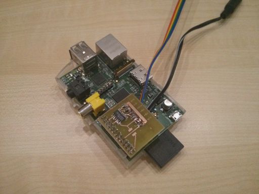
Most people connect their led string directly to the GPIO of the Raspberry Pi. This appears to be working for (almost?) all people. According to the [datasheet of the WS2801](http://www.adafruit.com/datasheets/WS2801.pdf) the data lines require 0.8*Vdd (= 4V for 5V led strings) for an input voltage to be considered as a high bit. This means that the 3.3V output of the GPIO is below the specs. Therefore, we decided to insert a line buffer between the GPIO and the led string based on a simple 74HCT series IC (using cascaded NAND (74HCT00), OR (74HCT32), or AND (74HCT08) ports). Note that it is important to use a chip from the HCT version as these are compatible with the 3.3V outputs of the Pi. A similar solution providing the same kind of buffering can be obtained from [HackerspaceShop.com](http://www.hackerspaceshop.com/raspberrypi-ws2801.html) and probably also from other shops. Below is a picture of the schematic and pcb layout we created and some photos of the result (click [here](Eagle_SpiBuffer.zip) to find the Eagle files). We added the option to power the pi using the power supply of the leds by placing an additional fuse, but due to a very bad Chinese power supply we decided to power the Pi and the leds separately and omit the fuse.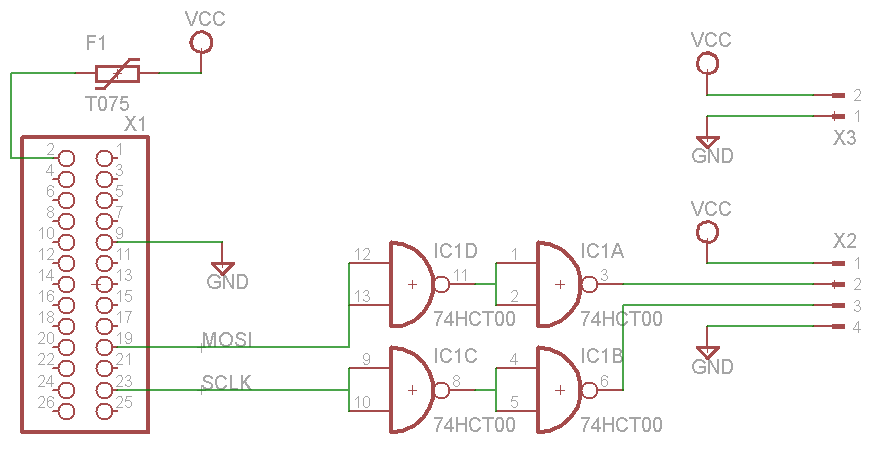
The solution was found unstable and is therefor discussed on another page (see Ws2812b).
The Raspberry Pi is equipped with several pins that serve as General Purpose IO. By switching them on and off very quickly a PWM (Pulse Width Modulation) can be created. By varying the ratio between the on and off time (aka Duty Cycle) the brightness of connected leds can be controlled. This does not however allow control of the color of the attached leds. To perform the PWM on the RPi Hyperion relies on Pi-Blaster (see [Pi-Blaster](http://marks-space.com/2013/09/23/software-pwm-on-a-raspberry-pi/)). The easiest 'mounting' is when you bought a flat led strip. These can simply be pasted to your TV with some double sided tape. Some of these strips even come with tape for this purpose. The difficulty with these strips is connecting the corners. This requires some extra soldering.There are actual corner connectors (or connection cables) available but I have no experience in their use and do not know how well they work. These have the potential to make your live really easy.
Attaching the leds behind the TV can be done in many ways: from simple cardboard frames to solid frames from aluminum profiles. We have chosen to create our frame from tubes for electrical wiring. An advantage of this method is that the leds (not the ones in the corner) can be turned a little to adjust the angle in which they are mounted. A photo showing the result is shown below. 