Power Supply Conversion
I got hold of a EMACS GIN-6350P server power supply that I want to use as a bench-top supply. I haven't been able to fine any low level documentation. Everything is at the level of how to install it into a redundant power chassis.

| Input | |
|---|---|
| Voltage | 100-240V |
| Frequency | 60-50Hz |
| Current | 8-5A |
| Output | |
|---|---|
| +3.3 | 20A |
| +5V | 35A |
| +12V | 22A |
| +5V (Standby) | 2A |
| -5V | 0.5A |
| -12V | 0.8A |
Total output 350W (max)
+5V & +3.3V shared total 35A (max)

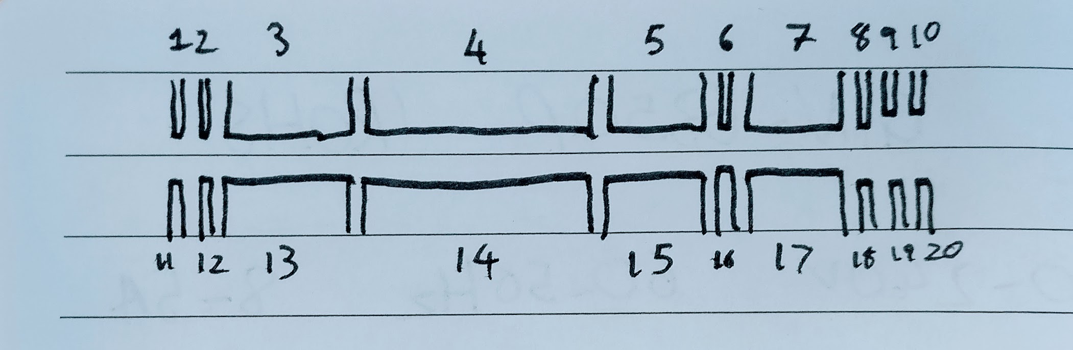
The connection is a "Card edge connector" that is 28 connectors top and 28 connectors bottom.
This is my current best guess at the interface.
| Pin | On State | Standby State | Shared Rail | Notes |
|---|---|---|---|---|
| 1 | -5V | |||
| 2 | 5V | X | ||
| 3 | 5V | X | ||
| 4 | GND | G | ||
| 5 | 3.3V | Y | ||
| 6 | 3.3V | Y | ||
| 7 | 12V | Z | ||
| 8 | ||||
| 9 | 6.14V | FanM or FanC or PWR_OK signal? | ||
| 10 | 5V | PS_On active low signal. Ground with 500Ohm resistor to turn on | ||
| 11 | 5V | 5V | Standby Power | |
| 12 | -12V | |||
| 13 | 5V | X | ||
| 14 | GND | G | ||
| 15 | 3.3V | Y | ||
| 16 | 12V | Z | ||
| 17 | 12V | Z | ||
| 18 | 3.3V | Maybe 3.3 sense signal? | ||
| 19 | 5V | FanM or FanC or PWR_OK signal? | ||
| 20 | 5V | FanM or FanC or PWR_OK signal? |
4.2.1 FanM Signal The FanM signal is an open collector, 2 pulse per revolution tachometer signal from the power supply fan. The signal stops cycling during a lock rotor state; the level can be either high or low. This signal allows the system to monitor the power supply for fan speed or failures. Implementation of this signal would allow a system designer to gracefully power down the system in the case of a critical fan failure. The monitoring circuit on the motherboard should use a 1k-Ohm to 10k-Ohm pullup resistor for this signal. The output should be fed into a high impedance gate for the motherboard implementation. Figure 11 shows a simple illustration of the basic circuit requirements. If this signal is not implemented on the motherboard, it should not impact the power supply function.
4.2.2 FanC Signal The FanC signal is an optional fan speed and shutdown control signal. The fan speed and shutdown are controlled by a variable voltage on this pin. This signal allows the system to request control of the power supply fan from full speed to off. Implementation of this signal would allow a system designer to implement a request-fan-speed control or shut-down during low power states such as sleep or suspend. The control circuit on the motherboard should supply voltage to this pin from +12VDC to 0VDC for the fan control request. • If a voltage level of +1 volts or less is sensed by the power supply at pin 2 of the optional connector, the fan is requested by the motherboard to shut down. If a voltage level of +10.5 volts or higher is being supplied to pin 2, the fan in the power supply is requested to operate at full speed. The fan control in the power supply may be implemented so that it allows variable speed operation of the fan, depending on the voltage level supplied. If, for example, a +6 V signal is sensed at pin 2, the power supply would operate the fan at a medium speed. If this signal is used for on/off control of the power supply fan, and speed control is not implemented in the fan control circuit of the power supply, the power supply fan should operate at full speed for any voltage level over +1VDC. The power supply should draw no more than 20 mA from pin 2 of the optional power supply connector. A pullup should be used internal to the power supply for this signal so that if the connector is left open, the fan will be requested to operate at full speed.
4.2.3 3.3 V Sense Line A remote 3.3 V sense line can be added to the optional connector to allow for accurate control of the 3.3VDC line directly at motherboard loads. Because of potential voltage drops across the connector and traces leading to the motherboard components, it may be advantageous to implement a 3.3 V sense line that remotely monitors the 3.3VDC power level at the load on the motherboard. The implementation of this signal should be such that if an NC condition is detected on this line, the default 3.3 V sense line on the main connector would be used for sensing the 3.3VDC voltage level.