This is a small project to understand how to use a fdcan on the nucleo stm32g474RE, and the MCP261FD as fdcan transceiver. The nucleo stm32g474re is required, but you can use any fdcan transceiver you wish.
This project uses platformIO with two framework : stm32cube and zephyr-rtos.
This framework uses code generated by stm32CubeMX and HAL library.
The exchange speed is 500kbit/s and the data length is 32 bytes.
This project was inspired by soarbear repository but it uses platformIO instead of stm32cubeIDE.
This framework will use the following files :
- src/main-stm32cube.c : main file
- stm32g4xx_it.c : interrupt handler
- syscall.c : to use printf
- lib folder : contains stm32cubeMX generated code
This framework uses CAN API driver from zephyr and is a real time operation system.
This is a code essentially inspired by a zephyr sample but I modified it to make the two on-board fdcan of the stm32g4 working together at 1Mbits/s.
The code is pretty complex if you don't know zephyr rtos or never worked with a RTOS, basically it uses thread, message queu and asynchronous operation. Here's some link that could helps understanding :
If you never worked with zephyr before you might need to follow some online tutorial first like this one from maksimdrachov .
This framework will use the following files :
- src/main-zephyr_rtos.c : main file
- zephyr folder : contains necessary files for zephyr like prj.conf, overlay for device tree and CMakeList.txt
First clone the project :
git clone https://github.com/Knden/FDcan_stm32G474re.git fdcan_project
there are two ways to use the project.
Open Vscode and install platformIO extension.
open the folder fdcan_project with visual studio code, and you should see these new icons at the botom :
![]()
Click on the arrow ➡️ to compile and flash the code. Make sure the nucleo is connected to the computer.
To select which framework to use, you should see at the botom you should see a folder icon named env:... it allows you to change between the two framework stm32cube and zephyr_rtos.

Here for example we are using the zephyr rtos framework, so we are flashing the code in main-zephyr_rtos.c.
If you wish to use only command line to flash the code, I recommend creating a virtual environment (make sure that you are in fdcan_project root) :
python3 -m venv venv
source venv/bin/activate
Then install platformIO with pip by installing the required packages in requirements.txt :
pip install -r requirements.txt
You can use the pio command line to flash the code to flash the code in the MCU.
pio run --environment stm32cube --target upload
pio run --environment zephyr_rtos --target upload
This code uses two fdcan of the stm32g474, the fdcan 1 and fdcan 2 thus you need two transceivers to use it. For this project I used the MCP261FD but you can use any fdcan transceiver you wish.

Here is the full schematic :
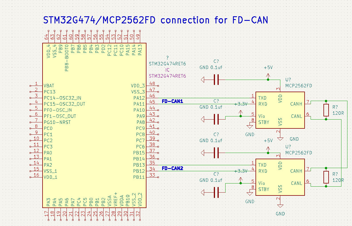
The source of the picture above comes from soarbear website. Here he uses the mcp2562 instead of the mcp2561 but the schematic is almost the same. The only difference is the presence of the split pin in the mcp2561.
depending on the framework used, the result is different.
The exchange speed is fixed at 500Kbits/s, the data length is 32 bytes. Here is how it works :
- Every 500 ms, the fdcan 1 is transmit a message to the fdcan 2, he increments the value of data by one.
- After receiving the 32 datas, will display it on the serial monitor.
The serial monitor allows you to see what the MCU display when we uses ̀printf.
If you are using platformIO on vscode just click on socket icon at the botom  and you'll see what is currently displayed by the serial monitor.
Else, you can choose your favorite software for serial monitor, the only thing you need to know is that the baudrate is 115200. I recommend the extension serial monitor for vscode.
Every 500 ms the fdcan2 will receive 32 datas from fdcan1 and display in the serial monitor. Here is what you should see at start :
preparing to send datas ...


 fdcan2 received data: 1, 1, 1, 1, 1, 1, 1, 1, 1, 1, 1, 1, 1, 1, 1, 1, 1, 1, 1, 1, 1, 1, 1, 1, 1, 1, 1, 1, 1, 1, 1, 1,
 fdcan2 received data: 2, 2, 2, 2, 2, 2, 2, 2, 2, 2, 2, 2, 2, 2, 2, 2, 2, 2, 2, 2, 2, 2, 2, 2, 2, 2, 2, 2, 2, 2, 2, 2,
 fdcan2 received data: 3, 3, 3, 3, 3, 3, 3, 3, 3, 3, 3, 3, 3, 3, 3, 3, 3, 3, 3, 3, 3, 3, 3, 3, 3, 3, 3, 3, 3, 3, 3, 3,
The data sent by fdcan1 are incremented each time.
To put it simply, the fdcan1 is sending an incremental counter to the fdcan2, then we retrieve this value to display it on the serial monitor/
The fdcan2 is sending a led status (ON or OFF) to the fdcan1, and we retrieve this data to either turn on or off the LED on the nucleo. We are making the led toggling here.
The exchange speed is 1Mbits/s.
The code is basicaly the same as the zephyr sample so you might find more informations there.
You should see the led blinking (means that fdcan2 sent the data with success) and a counter displayed in the serial monitor (fdcan1 sent data with success).
You should see the following datas displayed on the serial monitor :
*** Booting Zephyr OS build zephyr-v30700 ***
Change LED filter ID: 0
Counter filter id: 28
Counter received : 0
Counter received : 1
Counter received : 2
Counter received : 3
Counter received : 4
Counter received : 5