<< Back to Documentation Index
Start by removing the rails on the outside of the panel following the printed instructions, then snap apart the individual sensor boards.


You’ll probably want to use some pliers to clean up the spacer segments that were between the sensor boards.


Then insert the right-angle headers from the side with the pins labeled (and where “MOTOR” is visible). The pin headers should extend down past the bottom of the PCB.

Flip the PCB and solder the headers in place.


Insert and solder the connectors as shown. Note that both of the IDC connectors on the ends face the same way - notches facing left.

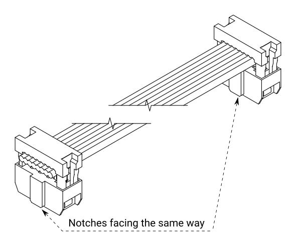
Insert the ribbon cable into a connector as shown, and gently clamp shut with a vise or pliers. Repeat with the other connector on the opposite end, making sure that both connectors face the same way - notches facing left.
(Not recommended, but you can optionally install the strain relief on the connectors: fold the ribbon cable back over the connector and install the plastic piece to clamp it down until it clicks. You’ll sacrifice some cable length and end up with a bulkier/taller connector, so I don’t think it’s worthwhile, especially since your cables shouldn’t be moving around much anyway.)
Solder the connectors into place (make sure the IDC connector notch faces the left, as indicated on the PCB)
T-Display Buddy


On the T-Display itself, you will solder the 2 rows of male headers (included in the box) to the T-Display, and then the whole module will plug into the matching female headers you soldered on the Buddy board.
You may notice a few empty spaces in the lower left of the T-Display Buddy PCB labeled C1 and C2 along with 3 through-holes; don’t worry, those are optional components for an advanced build and are not needed for a basic setup. See Standalone T-Display operation for more info.

Note: the T-Display often comes with a small Red/Black wiring harness with connector as well; it cannot be used alongside the Chainlink Buddy and should be discarded.
Breadboard Buddy (alternative to T-Display Buddy) If you’d prefer to use a different ESP32 module, you can use the Breadboard Buddy PCB to easily adapt the IDC cable to a breadboard.


We’ll start by connecting and testing just the Chainlink Driver, without connecting a power supply or any modules’ motors or sensors. We’ll add those later, after confirming that the basic electronics work.
T-Display
- Connect the ribbon cable from the Chainlink Buddy’s Output to the Chainlink Driver’s Input
- Connect a wire from the Chainlink Driver’s “Logic 3.3-5V” screw terminal to the “3.3V” screw terminal on the Chainlink Buddy
- Connect a wire from the Chainlink Driver’s “GND” screw terminal to the “GND” screw terminal on the Chainlink Buddy
- Connect a wire from the Chainlink Driver’s “Motor 5-12v” screw terminal to the “12V” screw terminal on the Chainlink Buddy
⚠️ Never connect a battery to the T-Display’s battery connector (small white connector on the bottom of the TTGO T-Display module) when using the Chainlink Buddy!

Breadboard (if you’re not using the T-Display Buddy) If you are using a different ESP32 module with the Breadboard Buddy rather than the T-Display Buddy, see the instructions in the full Chainlink User Guide.

Take an M4x10 bolt and nut and loosely assemble them on the spacer piece. Make sure the bolt can still spin somewhat freely. Set this aside.

Hold the 4 struts to form a box, with the stepped tab ends facing up…

… and then place the spacer on top with bolt facing up/out.

Spin the bolt/nut combo to so the nut’s edges are parallel to 2 of the strut tabs, and then place the wheel with hexagonal center hole onto the end.

Then attach the other wheel to the other end’s tabs. You may need to hold the whole assembly together at this point if the laser-cut parts are a bit loose.

I recommend using CA glue (with accelerator!) to permanently assemble the flap drum. My personal go-to glue is Bob Smith Industries thick CA glue (paid affiliate link, or use this non-affiliate link). Note: make sure you’ve installed the M4 nut+bolt earlier, as you won’t be able to install it after gluing!
Apply a small dot of CA glue to each joint between the center struts and the wheel ends (8 dots in total). You will have 30 seconds to a minute of working time at this step.


If the assembly is somewhat loose, make sure the wheel ends are not twisted, as this will cause flaps to hang at an angle! See photo below for why this is problematic:

When the drum is fully assembled and you’ve ensured it’s not twisted, spray CA accelerator to quickly lock the glue in place. If the parts are particularly loose, you may want to hold the assembly together with gloved hands while you spray CA accelerator.

💡 Important CA glue tip: If you don’t use accelerator, you’ll likely end up with a white haze or residue all over the acrylic parts — this is caused by small amounts of CA glue vaporizing and curing with the moisture in the air, which then gets deposited onto your parts (and surrounding table, computer, etc!) to make a permanent white-ish haze. I’ve never had issues with CA haze/fogging when using Bob Smith Industries glue with the included accelerator spray, which is why I recommend it! (paid affiliate link, or use this non-affiliate link)
After waiting a few minutes for the accelerated CA glue to cure, use an allen key to tighten the internal M4 bolt and lock it in place.

Take the wider of the side enclosure pieces (with a rounded rectangular hole cut out of the middle) and insert the motor’s cable through the hole in the orientation shown below.


Then place the sensor PCB over the motor, and insert 2 M4x10 bolts into the motor mount holes.


Flip the assembly over and start threading a nut onto each bolt, then use an allen key to finish tightening the nuts.


Next we’ll install the magnet into the flap drum. The orientation of the magnet is critical, as the sensor only works with one pole of the magnet and not the other!
Luckily we can use the LED on the sensor PCB to help determine the right way to install the magnet.
Plug the sensor into your Chainlink Driver, and connect the Chainlink Driver to your ESP32/Chainlink Buddy, ensuring you’ve connected the 3.3v logic power screw terminals.

When you hold up the magnet, the LED should light for one side of the magnet and not the other.


Install the magnet into the flap drum in the orientation that caused the LED to light.
I’ve found that attaching the magnet to one jaw of a set of pliers and then gently pressing it into the flap drum works well — DO NOT FORCE IT if it requires more than a tiny bit of pressure, as you will crack the acylic; use a file to widen the hole and then try again.


Double-check you got the magnet orientation correct when installing the flap drum onto the motor. Again, it should gently press-fit onto the motor shaft; use a file to widen the hole first if it requires too much force to press into place.

If the magnet is a little loose, you can add a drop of CA glue on the back side (from the inside of the drum) to lock it in place.
The top and bottom pieces are interchangeable with each other. Find the matching tabs and slots of the top piece and the left side (with the motor)…

… insert a nut into the notch in the top piece (I like to support it from behind with a finger as shown below) and screw in an M4x10 bolt to connect the pieces.

Repeat that process with the bottom piece, and then attach the right side piece as well.

Before installing the front face, insert the M4x10 flap backstop bolt in the middle of the slot on the right side piece and secure in place with a nut. You can fine-tune the position later if desired, but the middle is usually a good starting point.

Now attach the front face using M4 bolts/nuts to secure it to the top and bottom pieces.

Now you can install the flaps. The first flap you install should be blank and the bottom half of the letter “A”.

Install the first flap into the position shown below — 90 degrees “ahead” of the magnet on the flap drum. (this position technically isn’t critical since the home position is software-calibrated later, but it’s a nice convention to keep the modules consistent with each other)


To install a flap, let it rest between your index and middle fingers, and press on the middle with your thumb to bend the flap. Insert one of the flap’s pins into the flap drum, then carefully align the other pin and gently release pressure from your thumb to insert the second pin as the flap unbends.
Repeat with the next 51 flaps, making sure to confirm the ordering as you do so.

- Download and install Microsoft Visual Studio Code
- Follow these steps to set up Platform IO and the splitflap code:
- Install the Platform IO extension
- Choose “Clone Respository” in the Explorer sidebar and enter the git repo URL:
https://github.com/scottbez1/splitflap.git - Once it's done cloning, select the option to open it
- You may need to choose to “Trust” the folder to allow the Platform IO extension to run.
You’ll need to configure NUM_MODULES in platformio.ini to match the number of modules supported by the Chainlink Drivers you have connected. So for a single Chainlink Driver, set it to 6.
[env:chainlink]
extends=esp32base
build_flags =
    ${esp32base.build_flags}
    -DCHAINLINK
    -DNUM_MODULES=6
- Mac Users: you will likely need to install updated drivers for the CH9102 USB-serial adapter used on newer versions of the ESP32 T-Display: https://learn.adafruit.com/how-to-install-drivers-for-wch-usb-to-serial-chips-ch9102f-ch9102/mac-driver-installation
- To upload code to the ESP32 T-Display from VS Code, you’ll need to (see screenshot below):
- Open the Platform IO sidebar (click the alien icon on the left)
- Click the “env” button at the bottom of the window and then in the dropdown at the top of the screen…
- …select “env:chainlink” as the environment - this will set up code completion and syntax highlighting for the ESP32
- in the Platform IO sidebar, expand the “General” section, and click
Upload and Monitor

- If you reset the ESP32, you should see the LEDs on the Chainlink Drivers blink quickly and a message in the serial monitor that loopbacks are ok. If you see a loopback error message, troubleshoot that before continuing.
Motors
- Plug into the white connectors. Note that module connections are laid out from right-to-left since the Chainlink Driver PCB is intended to sit behind the modules, so the first module plugs into position “A” on the right side of the PCB
Sensors

- Plug sensor cable into corresponding 3-pin header
- Ground (black) should be on the left, labeled “-”
- Signal (usually white or yellow) should be on the right (toward the “Input” side), labeled “S”
Power The ESP32 and 3.3v electronics on the Chainlink Drivers are typically powered by the USB connection to a computer. 12V power for the motors is supplied via a separate power supply.
Note: avoid turning on 12V power when the ESP32 is not running! Doing so could damage your motors or worse, as the motor coils could be "stuck on" if the ESP32 is not running.
T-Display
- You can plug a DC 12v barrel jack into the T-Display Buddy when using 1 or 2 Chainlink Drivers for up to 12 modules.
⚠️ For more than 2 Chainlink Drivers, the barrel jack cannot handle enough current, so you should instead connect your power supply directly to the Motor Power terminals of the first Chainlink Driver. Make sure you are using the appropriate wire gauge, and never chain power to more than 6 Chainlink Drivers https://www.dropbox.com/s/4xpvtycwrw21g0e/chainlinkBuddyWiringv1.1.pdf?dl=0
Breadboard
- Connect your power supply directly to the Motor Power terminals of the first Chainlink Driver. Make sure you are using the appropriate wire gauge, and never chain power to more than 6 Chainlink Drivers
For further wiring info, see the full Chainlink User Guide.
- Turn on your 12V supply and plug the ESP32 into your computer.
- You should see the modules start to find their home positions.
- If none of modules move, try restarting the ESP32. If they still don’t move, turn off your 12V supply and see the troubleshooting section
- In Chrome or Edge (unfortunately Firefox will not work, as of 2024-10-05), go to https://scottbez1.github.io/splitflap/ and connect to your display via Web Serial
- If a module is showing as an orange square, you should first try re-homing the module by left-clicking it. You should see the module spin and find its home position. If this does not resolve the sensor error, see the troubleshooting section
- Right-click a module to open the calibration flow, and follow the instructions to complete calibration. Save the calibration before continuing to calibrate the other modules.
- If saving the calibration fails, see the troubleshooting section
- Modules don’t move at all when the ESP32 and 12V supply are turned on
- Troubleshooting steps:
- Run the “Monitor” PlatformIO action in VSCode and then press the reset button on the ESP32. You want to see a message like
{"type":"init", "num_modules":6}and not any messages about loopback errors (see section below if you do see aLoopback ERROR) - Make sure your screw terminals are securely clamped onto the appropriate wires
- Use a voltmeter to confirm that there is 11-13V measured between the Motor and GND screw terminals on each Chainlink Driver board
- Run the “Monitor” PlatformIO action in VSCode and then press the reset button on the ESP32. You want to see a message like
- Troubleshooting steps:
- Saving module calibration fails
- Symptoms:
Failed to open config fileorFailed to mount FFatmessages when saving calibration - Troubleshooting steps:
- In VSCode, use the PlatformIO action to erase the flash on your ESP32, then re-upload the firmware and try calibration again
- Symptoms:
- Bad chainlink data signal -
Loopback ERROR- Symptoms:
Loopback ERRORlog message. This means the control signals to the motors or from the sensors are not working along the chain of Chainlink Driver boards. - Troubleshooting steps:
- Check all of your solder joints, especially those on the IDC connectors, to make sure they are solid and not bridged
- Make sure the IDC ribbon cable connectors are fully clamped onto the ribbon cables
- Check all of the screw terminals are securely clamped onto the appropriate wires
- Make sure the NUM_MODULES variable in platformio.ini (under the
env:chainlinksection) is set to 6 times the number of Chainlink Drivers you have connected - Press the reset button on the ESP32 and confirm that the red LEDs on the Chainlink Drivers each flash sequentially once
- Symptoms:
if you have questions not covered here, please reach out in the splitflap Discord server.
Link disclosure: As an Amazon Associate I earn from qualifying purchases at no cost to you. (I’ve also chosen to include non-affiliate links next to every affiliate link should you prefer to avoid using affiliate links)