Tutorial06
Introduction
The object of this tutorial is to guide you through the process of solving an inorganic crystal structure, using the compound ZrW2O8 as an example. This compound, zirconium bis(tungstate), contains zirconium ions (pink) and tungstate tetrahedra (green, with oxygen atoms shown in red). For this tutorial, it is assumed that you have already completed Tutorial 1. In the process of this tutorial you will learn how to:
-
Solve the structure of an inorganic compound.
-
Handle multiple structural fragments as separate z-matrices.
-
Cope with the complications of high symmetry space groups.

Data
The data set Tutorial_6.raw is a laboratory x-ray diffraction data set collected at room temperature by John Evans. The incident wavelength was 1.54060 Å.
Stage 1: Reading the data
-
Open DASH and select the directory where the data resides.
-
Select View data / determine peak positions and click Next >.
-
Select the file Tutorial_6.raw using the Browse... button.
-
Click Next >.
-
Check that the wavelength and radiation source have been set correctly and click Next >.
-
The default settings shown in the Background Subtraction window are good enough for this simple background. Click Next >.
Stage 2: Examining the Data
This data set is very clean, with a very low background and sharp reflections, so we do not want to throw away any of the high resolution reflections. Change the settings to truncate the data to a resolution of 1.0 Å. Subtract the background using the default window setting of 100. Click Next >.
Stage 3. Fitting the Peaks to Determine the Exact Peak Positions
Select the first 20 peaks using the method described in the first tutorial.
Here is a guide to the approximate positions (2θ) of the first 20 peaks:
| 16.7803 | 19.3916 | 21.6881 | 23.7869 | 27.5389 |
| 29.2538 | 30.8623 | 32.4090 | 35.3199 | 36.7033 |
| 39.3372 | 40.5986 | 41.8329 | 43.0303 | 44.2036 |
| 45.3575 | 46.4954 | 48.6816 | 49.7570 | 50.8086 |
Stage 4. Indexing
A typical run of DICVOL, if the selected peaks were very close to those given in the previous stage, should return a cubic cell as the best fit, with:
a = b = c = 9.1547 Å, V = 767.23 Å3
Figures of merit: M(24) = 160.1, F(24) = 154.6
A number of other possible cells are likely to appear with lower symmetry. Select the cubic cell as this should give the best figures of merit.
Stage 5. Stop and Think
Does the cell make sense? There is a very approximate method of estimating molecular volume using 15 Å3 per C, N, O atom and 25 Å3 for heavier atoms. So for this compound, ZrW2O8, we estimate the formula unit volume to be 195 Å3, so 4 formula units per cell would need a volume of approximately 780 Å3. The DICVOL cell volume of 767 Å3 suggests that we have roughly four formula units per cell.
Stage 6. Checking the Cell and Determining the Space Group
The space group that is automatically selected for the cubic crystal system is P23. A quick scan of the diffraction pattern and tick-marks for the predicted reflections should show that the majority of tick-marks correspond to observed peaks. This suggests that the space group is either correct, or quite close to the correct one. Try selecting some of the other space groups in the list for the cubic crystal system and looking at the correlation between tick-marks and peaks. You will see that the majority of space groups produce regions where there are no tick-marks, but there are observed peaks, e.g. F23, I23, I213, Fm-3, Pa-3.
The correct space group for this crystal structure is actually P213. Have a look at the predicted peak positions for this space group and check that these correspond to the observed peaks. To check that this is correct, run the space group determination tool. This should confirm that the space group is primitive and that the only systematic absences present indicate a 21 screw axis, which only leaves two possible space groups - P213 and P4232. The structure will not solve, however, in P4232.
Stage 7. Extracting Intensities
Select a series of isolated peaks across the diffraction pattern (e.g. 16.77, 21.69, 32.41, 45.36, 51.85, 62.50) as shown in previous tutorials. The peak picking algorithm may continue to the Pawley refinement step after you have only chosen 5 or 6 peaks if it deems the peaks chosen acceptable. The initial 3 cycles of refinement should give a Pawley 2 of around 1.2; accept these three cycles. The next five cycles of least squares refinement should bring the Pawley 2 value down slightly further. Refinement of the peak shape parameters is unlikely to improve the refinement for this data set. Your final 2 parameter should be in the region of 1.0 - 1.2.
Accept your best Pawley fit, making a note of the 2 value, and save it as Tutorial_6.sdi.
Stage 8. Building the Preliminary Model
In order to solve the crystal structure we need to define a starting model. The oxygen atoms have much less electrons than the Zr and W atoms and therefore scatter x-rays more weakly. This means that it is sensible to determine the positions of the heavy atoms first before attempting to determine the light atom positions. A starting model for the heavy atom structure solution can therefore be defined as simply free Zr and W atoms. These can be set up using your preferred model building software, or using a file supplied with the tutorial, Tutorial_6-atoms.mol2.
Stage 9. Setting up the Structure Solution Run
-
Start DASH as before and select Simulated annealing structure solution from the Wizard.
-
Select the Tutorial_6.sdi file.
-
Click on the
 icon and select Tutorial_6-atoms.mol2 (the file that you created
in Stage 8); three Z-matrix files will be automatically generated.
icon and select Tutorial_6-atoms.mol2 (the file that you created
in Stage 8); three Z-matrix files will be automatically generated. -
At this point DASH will identify that there are 9 independent parameters; three parameters each for the positional coordinates of the three atoms (1 Zr atom and 2 W atoms). The parameters will be then be listed along with their initial values and parameter bounds when you click on Next >. Note that each atom is free to move anywhere in the unit cell and that each atom has a full occupancy. As DASH does not have ‘anti-bumping’ constraints, multiple atoms are free to move to the same site.
-
Click Next > to access the Simulated Annealing Protocol window. Change the Profile chi-sqd multiplier to 6.0, leave the remaining variables at their default values, click Next > and then click Solve >. This set of SA runs will take a little while, but should converge eventually to a solution with a profile 2 in the region of 5.75. Ideally each SA run should produce a solution with approximately the same value of 2, suggesting that this is the correct solution and is reproducible.
Stage 10. Analysis of Preliminary Solution
-
Take a look at the solutions found by DASH individually by clicking on the View buttons for each row in the Analyse solutions table.
-
It should be obvious that the Zr atoms are aggregating on the origin, or one of the symmetry equivalent positions to the origin in each case (e.g. 0, 0.5,0 or 0.5, 0, 0.5 etc.).
-
The W atoms are also seen to aggregate, but these sit on the 3-fold axes of the unit cell. This can be seen by turning on the symmetry elements in Mercury - click Display > Symmetry Elements... The 3-fold axes should be shown as green vectors with no arrows on.
-
In this case the fact that the atoms were each assigned full occupancy, rather than the correct occupancy (which should be 1/3 as they each reside on the 3-fold axis) was not a problem because the ratios of the atomic occupancies are correct. The incorrectly high occupancies used are compensated by changes in the scale factor. Once the oxygens are included it will become important to use the correct occupancies of 1/3 for the Zr and W atoms.

-
The fit to the experimental diffraction pattern still shows a lot of differences as we have not found the positions of the oxygen atoms.
-
We can now use these positions that we have determined for the heavy atoms in the next cycle of the structure solution in order to find the light atom positions.
-
The coordinates of a general position on the 3-fold axis can be written as (x, x, x) - we have seen that the Zr atom resides at the position (0, 0, 0). The positions of the two W atoms can be found by clicking in Mercury on More Info > Atom List... Inspection of the W coordinates should show that the average positions of the two atoms are (0.6, 0.6, 0.6) and (0.3412, 0.3421, 0.3412) respectively.
-
Click < Back to return to the DASH Wizard welcome window and select Simulated annealing structure solution. Click Next > to continue.
Stage 11. Building the Full Model
-
In order to fully solve the structure and determine the light atom positions we now need to set up a more complicated structural model. We will continue to use a free Zr atom and use a tetrahedral geometry for the tungstate moieties. As the W atoms are each on a 3-fold axis, the rest of the tungstate tetrahedra must be represented by one partially occupied O atom on the 3-fold axis and one fully occupied O atom lying off the 3-fold, with the remaining two O atoms generated by symmetry.
-
For the tungstate tetrahedra we can therefore use O-W-O fragments generated with ideal O-W bond lengths and an ideal tetrahedral O-W-O bond angle. These fragments can be generated using your preferred model building software, or using a file supplied with the tutorial, Tutorial_6-atoms.mol2.

-
The structure solution window will still show the same .sdi file as used previously along with the atom z-matrices which we used in the preliminary solution.
-
Click on the
 icons to remove each of the atomic z-matrices. Next, click on the
icon and select Tutorial_6-frags.mol2; three Z-matrix files will
be automatically generated.
icons to remove each of the atomic z-matrices. Next, click on the
icon and select Tutorial_6-frags.mol2; three Z-matrix files will
be automatically generated. -
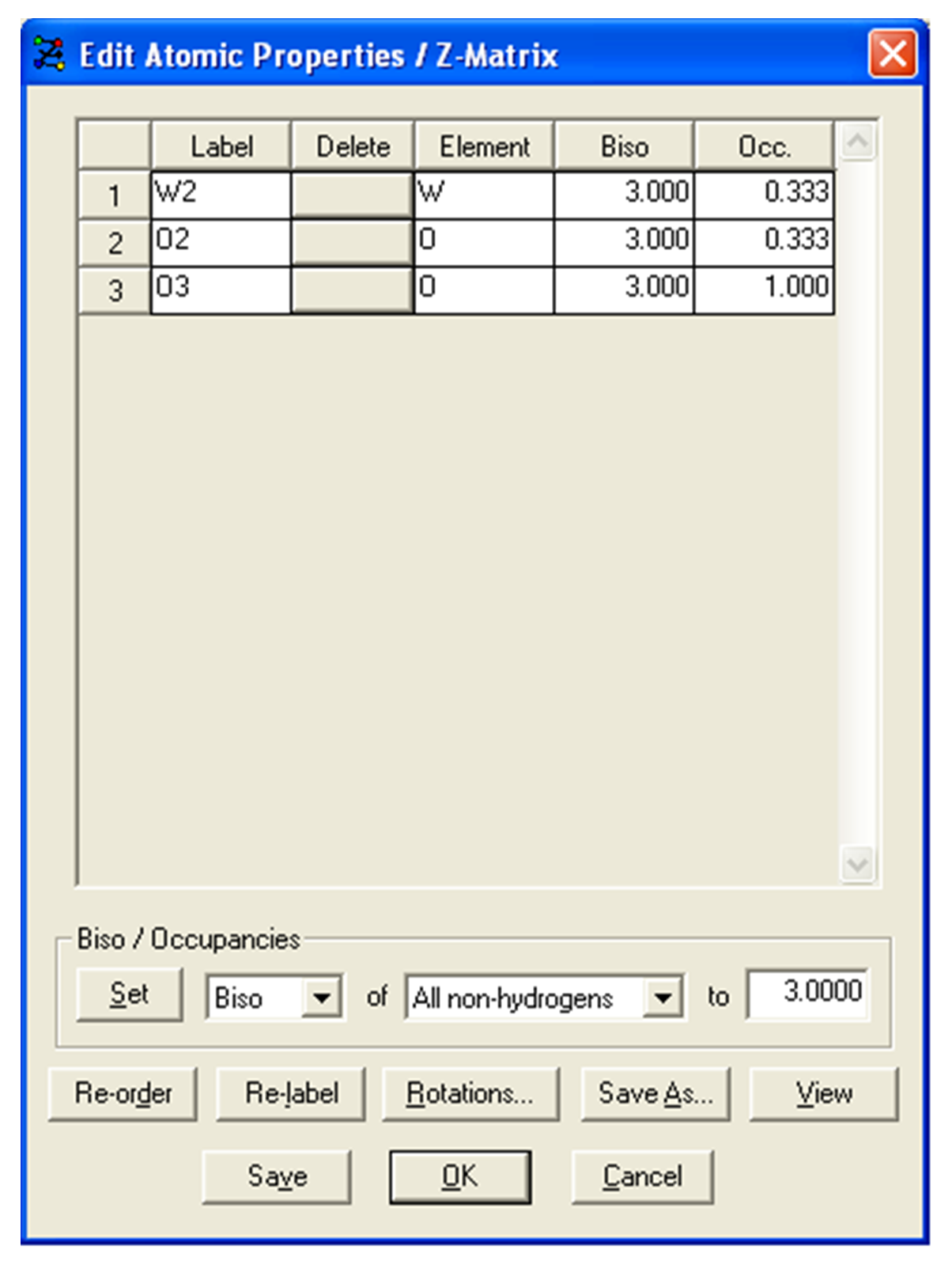
We also need to edit the occupancies of the atoms on special positions. To do this, click Edit in the row for the z-matrix. The atoms Zr1, W1, O1, W2 and O2 should be set as an occupancy of 0.3333 and the remaining two atoms (O3 and O4) should be left with a occupancy of 1.0 (e.g. see below).
- The DASH Wizard will also confirm that you now have 15 independent degrees of freedom. Click Next > to continue.
Stage 12. Setting up the Full Model Structure Solution
-
In the Parameter Bounds window we now want to use the information gained during the preliminary solution to fix the coordinates of the heavy atom positions.
-
The Zr atom, as found earlier, sits on the origin. Fragment 1 corresponds to the free Zr atom, so we can change the initial x(frag1), y(frag1) and z(frag1) values to 0.0 and click on the checkbox in the F column for each of these rows to fix the coordinates.
-
Fragments 2 and 3 correspond to the two O-W-O fragments and we can fix the coordinates of the W atoms by simply putting in the initial values of x, y and z for fragments 2 and 3 as the W atom corresponds to the origin coordinates for the fragment.
-
Choose the coordinates of fragment 2 to be (0.6, 0.6, 0.6), fragment 3 to be (0.3412, 0.3412, 0.3412) and set these parameters to be fixed as well using the checkboxes in the F column. The rows for these fixed parameters should now all be greyed out (see figure below).

-
Click Next > to continue.
-
In the Simulated Annealing Protocol window, choose a lower Profile chi-sqd multiplier (for example 1.5 or 2.0) this time as we expect the fit to the experimental data to be even better now as we are modelling the full structure. Also the O atoms have so few electrons compared to the Zr and W atoms, which means that the O atom positions only have a small effect on the diffraction pattern, so the correct solution is harder to find.
-
Click Next > and then Solve > to start the Simulated Annealing process.
-
This SA run is also likely to take a while as the differences between correct and incorrect solutions are quite small in terms of the effect on the profile.
Stage 13. Examining the Final Structure
-
The Analyse solutions window will now show the results of the SA runs. The runs may not all have reached the same structural minimum and this can be seen by the range of final Profile chi-sqd values for the runs. Correct solutions should be identified by the lowest Profile chi-sqd and Intensity chi-sqd values.
-
Take a look at the solutions found by DASH for the full structure by clicking on the View button for one of the top few solutions. Using the Packing feature of Mercury turned, it should be possible to see that the tungstate moieties have formed into nicely shaped tetrahedra, although the O1 and O2 atoms may be slightly off the 3-fold axes. The ZrO6 moieties are also formed into undistorted octahedra.
-
The following figure shows an image of the solved structure in Mercury and the equivalent view displayed using ZrO6 and WO4 polyhedra in the DIAMOND structural visualiser.

-
Clicking on the Show overlay button in the Analyse Solutions window should also show that the solutions fit with each other very well, which suggests that the solution is reproducible.
-
In order to refine the structure in a meaningful manner there is a built-in rigid-body Rietveld refinement module (see Overview of DASH in Batch/GRID Mode). To start a Rietveld refinement from one of the structure solutions simply click on the Rietveld button for that row of the Analyse Solutions table and choose the refinement package that you wish to use.
-
Careful refinement of the bond angles and bond distances should cause the tungstate moieties to assume a better shape.
References
DICVOL Program:
D. Louer & M. Louer (1972) J. Appl. Crystallogr. 5, 271-275.
A. Boultif & D. Louer (1991) J. Appl. Crystallogr. 24, 987-993.
Extinction Symbol Program:
Markvardsen, A.J., David, W.I.F., Johnson, J.C., Shankland, K. (2001)
Acta Cryst., A57, 47-54.
Powder crystal structure ZrW2O8 (ICSD code
83267):
T. A. Mary, J. S. O. Evans, T. Vogt & A. W. Sleight (1996) Science
272, 90-92.
DIAMOND Program Version 3.0:
Crystal Impact, Crystal Impact GbR, Postfach 1251, 53002, Bonn, Germany
(2004).
[^1]: This initial value is determined from a sketched model and is reasonably far from the true angle for this structure. If the bimodal ranges indicated are entered and Ok is pressed a dialogue box will pop up and inform you that the initial value does not fall within the defined ranges. To proceed, change the initial value of this torsion angle to for example, 70.00.